STPA-Sec Analysis using Chiller
Industrial Control Systems (ICS) become increasingly software-intensive. For example, cyber-physical systems are electronic control systems that control physical processes and machines such as, motors and valves, in an industrial plant using Information and Communication Technologies (ICT). The advances in computing power and network transmission speeds, coupled with a decrease in hardware cost, has enabled new applications of ICT in industrial settings to improve efficiency of the underlying physical processes. The resulting displacement of traditional analog and mechanical devices with software-intensive control systems has inadvertently intertwined the architecture of physical processes with cyberspace; thus, exposing them to new risk possibilities. In this analysis, we demonstrate the use of Systems-Theoretic Process Analysis (hereinafter referred to as STPA) to identify cyber-vulnerabilities that have the potential to cause physical damage in industrial control systems using a chiller control system as an use-case. It is shown that the method provides a well-guided and structured analysis process to unveil new cyber vulnerabilities that span not only technical aspects but also the broader socio-organizational system. The method ties system-level losses to violation of constraints at both the component-level as well as the process level and provides recommendations to make the system more resilient by defining additional countermeasures to control vulnerabilities in the system.
System Information
The central focus of this analysis step targets cyber-safety STPA analysis (hereinafter refrred to as STPA-Sec) of Chiller Control. The following picture is the system information screen where the abstract for the analysis will be described in general.
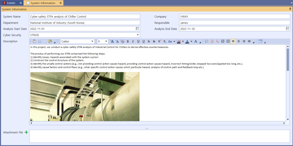
Picture 1. System information of STPA-Sec of Chiller Control
1. Identify Losses & Hazards
STPA analysis takes four steps, the first of which is ‘identify Losses & Hazards’. The screen presented below is for identifying Losses.
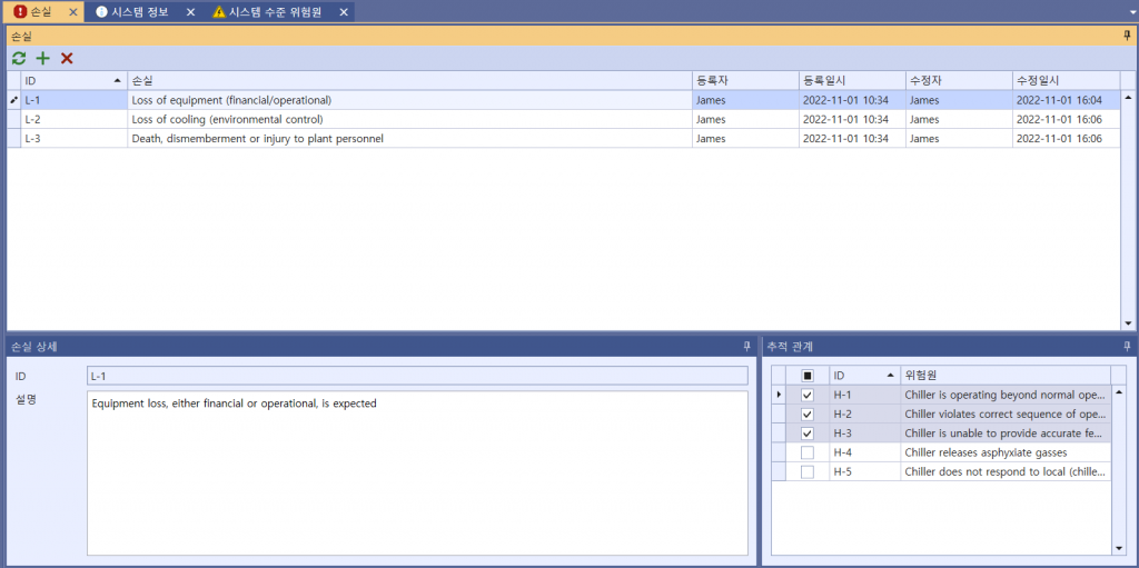
Picture 2. Identifying Losses of chiller’s STPA-Sec
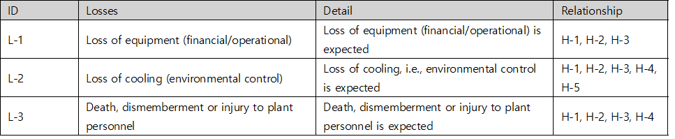
Table 1. Losses table of chiller’s STPA-Sec
For a system of chiller’s STPA-Sec, 5 Hazards can be identified, each of which then creates a traceable relationship with Losses. The identified hazards are as follows :
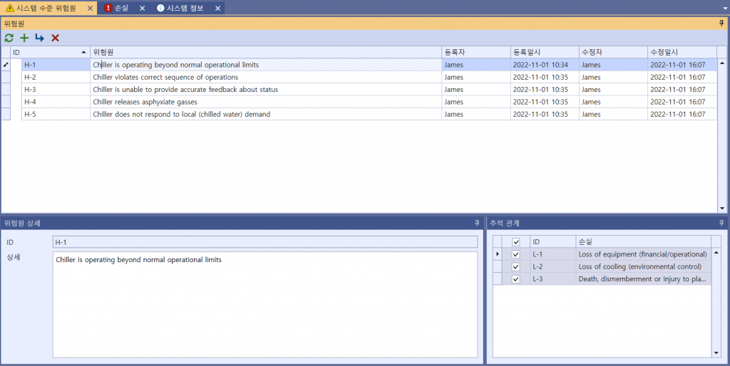
Picture 3. Identifying Hazards of chiller’s STPA-Sec
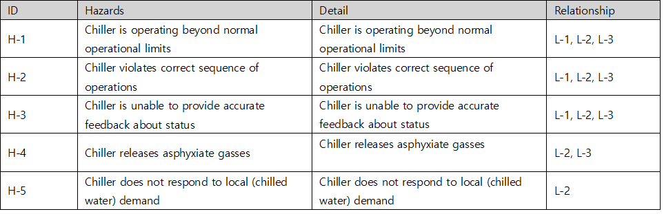
Table 2. Hazards table of chiller’s STPA-Sec
For a chiller’s cyber threats, 8 Constraints can be identified, each of which then creates a traceable relationship with Hazards. The identified Constraints are as follows :
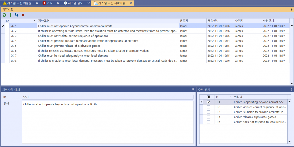
Picture 4. Identifying Constraints of a chiller’s cyber threats
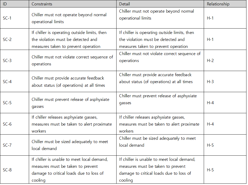
Table 3. Constraints table of chiller’s cyber threats
2. Control Structure Modeling
The second step out of the four is to build a model of the system called a control structure. A control structure captures functional relationships and interactions by modeling the system as a set of feedback control loops. The control structure usually begins at a very abstract level and then is through iteration refined to capture more detail about the system. This step is essential regardless of whether it concerns safety, security, privacy, or other any other properties. A high-level control structure of the system under analysis is illustrated below. There are several control loops captured in the control structure, such as the control loop between ‘Operator’ and ‘DSC’, between ‘Chiller PLC Controller’ and ‘VFD Control Unit’ and between ‘Cooling Capacty’ and ‘Chilled Water Temperature Sensor’.. etc. The control structure at this abstraction level includes many CAs.
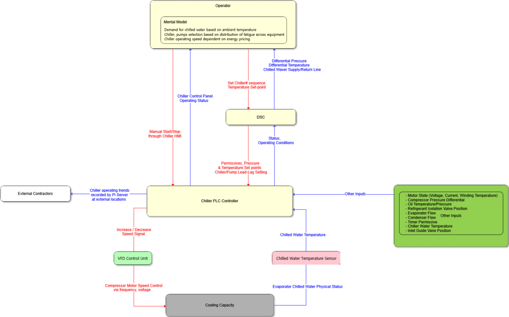
Picture 5. STPA Control Structure Diagram for Chiller System
3. Identify UCA
The third step out of the four identifies Unsafe Control Action (UCA). Accorting to STPA methodology, UCA is created into four types (Not providing causes hazard / Providing causes hazard / Too early, too late, out of order / Stopped too soon, applied too long). The associated UCAs for a Control Actions will be given in the below picture as an example.
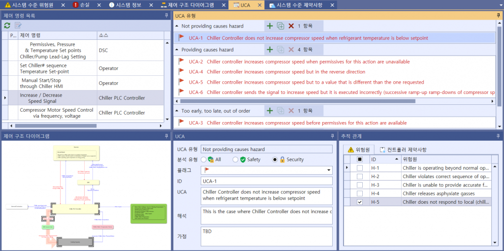
Picture 6. Identifying UCAs of Chiller System
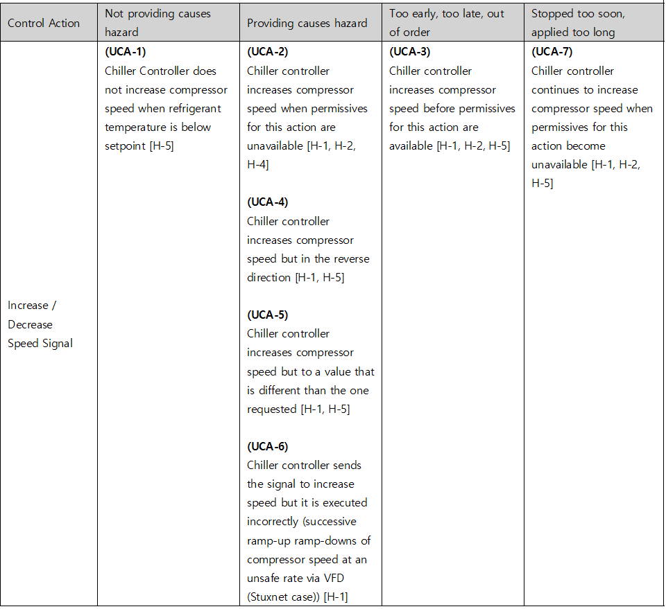
Table 4. UCA table of Chiller System’s cyber threats
4. Identify Loss Scenario
Once you have identified an UCA, you should create a scenario that causes it. STPA refers to this as a Loss Scenario and can be written by referring to a Guide Word that causes a Loss Scenario provided by the Handbook. Below are some of the possible Loss Scenario in UCA2 : Chiller controller increases compressor speed when permissives for this action are unavailable. You can additionally find lock symbols in the red column on the picture below, meaning each UCA’s relevance to cyber-safety, while the UCA under a shield symbol indicates its attachment to overall safety.
(The shield UCA is provided only for example – it’s NOT part of the logic)
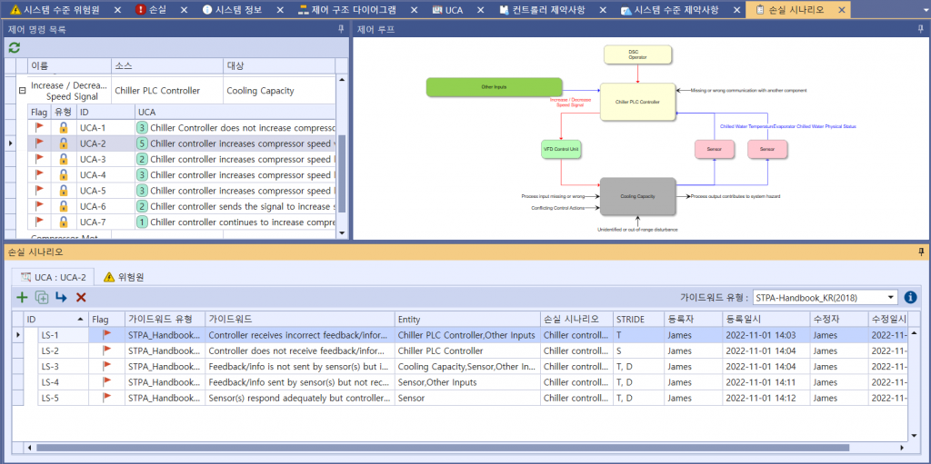
Picture 7. Identifying Loss Scenarios of Chiller System’s cyber threats
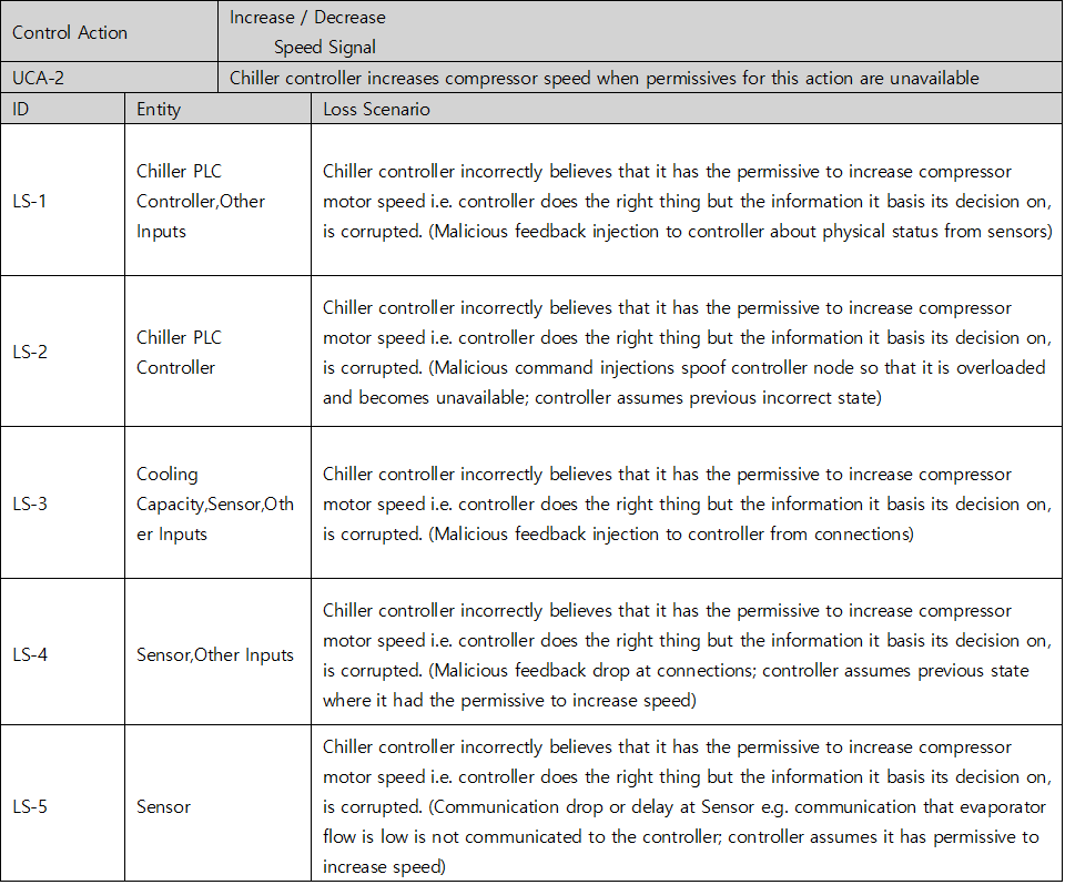
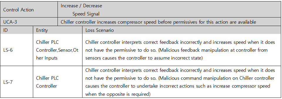
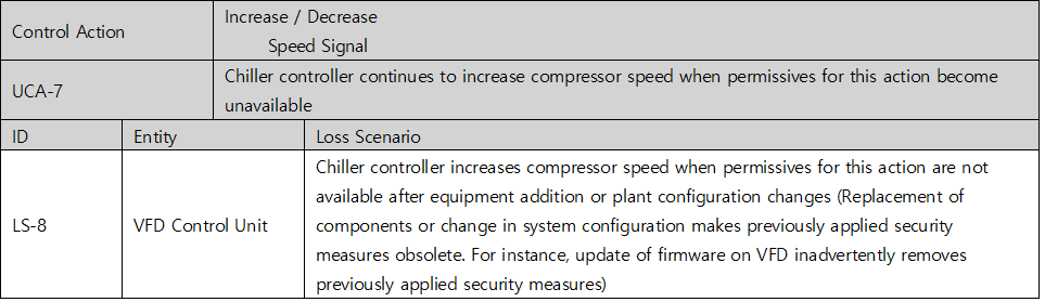
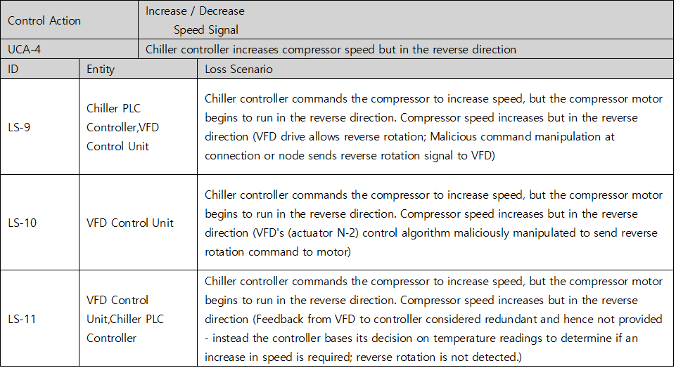
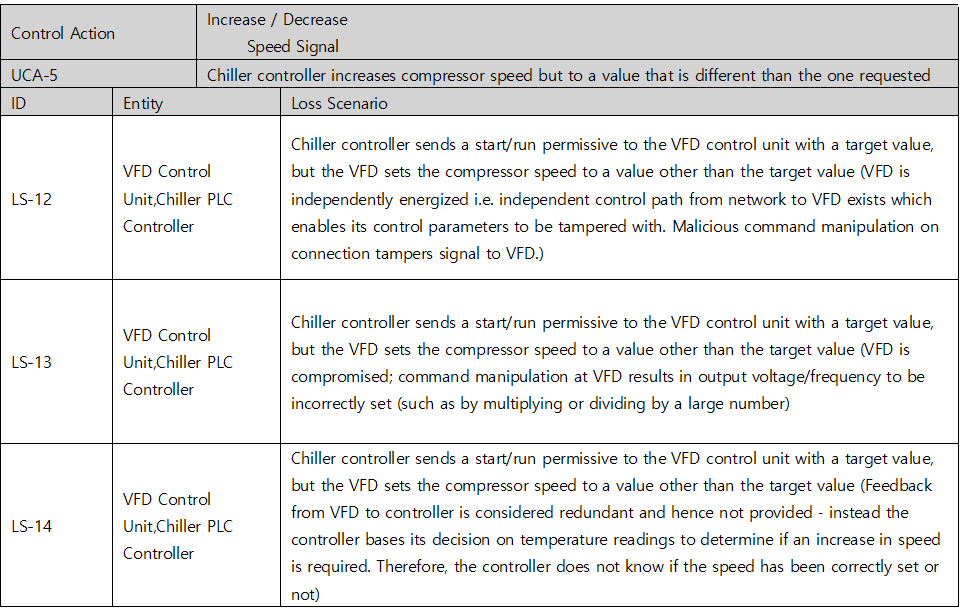
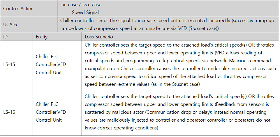
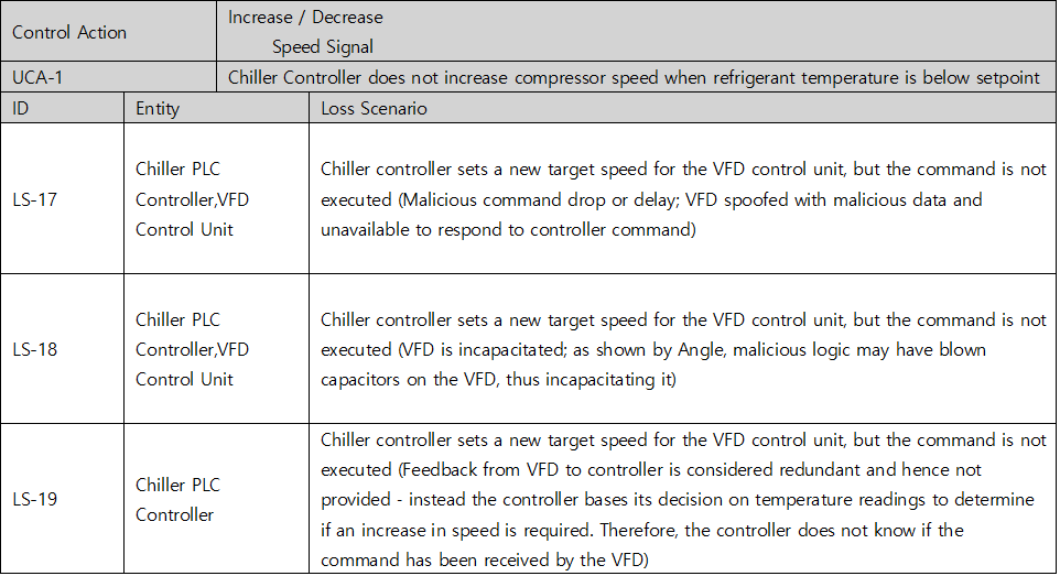
Table 5. Loss Scenario table of Chiller System’s cyber threats
Once you have identified a Loss Scenario, you then can create a Countermeasure to prevent every related Loss Scenario there is by creating a connection between them.
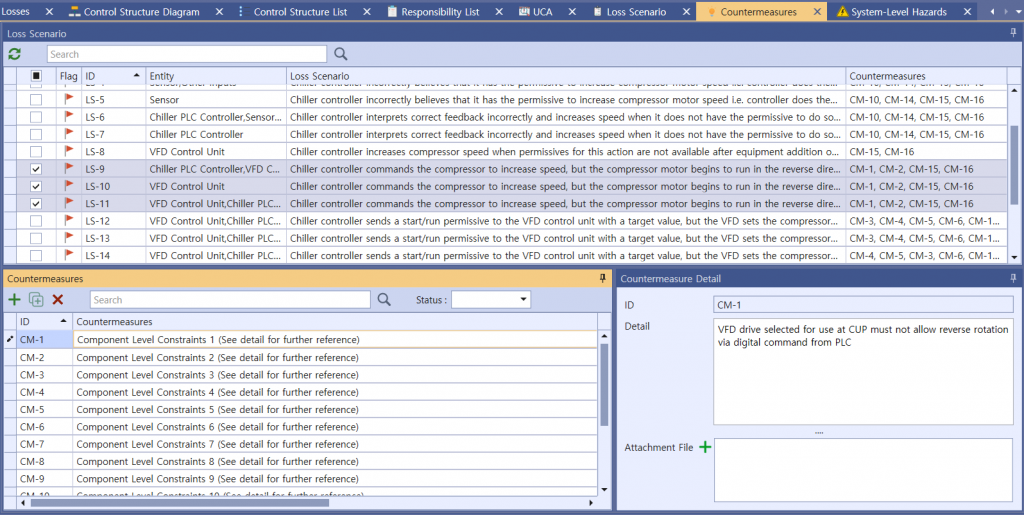
Picture 8. Identifying Countermeasures of Chiller System’s cyber threats
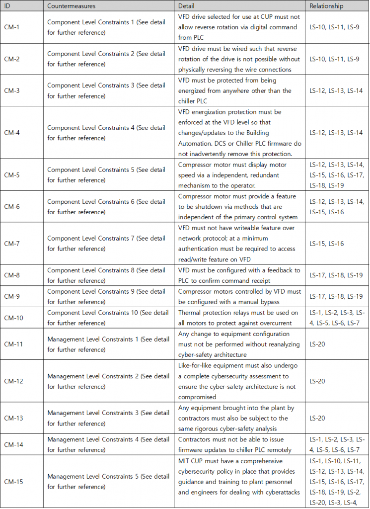
Table 6. Countermeasure table of Chiller System’s cyber threats
Conclusion
In this STPA analysis, we have analyzed a single representative control loop (the compressor motor speed control) of an archetypal industrial control system (i.e. the centrifugal chiller) at a small-sized power plant in the context of cyber-security using a vulnerability analysis method based on Systems Thinking. Starting with system-level losses and hazards, we traced the functional control structure of the plant and abstracted out the compressor capacity control loop for a detailed analysis of a single control action under various system states. We then generated loss scenarios under which the unsafe control actions would result in system-level losses. Finally, we proposed new ‘countermeasures’ at various layers of the functional control structure (starting at the process layer and going all the way back up to the enterprise and regulatory level) to prevent the system from entering unsafe system states.
Shaharyar Khan, Stuart Madnick, and Allen Moulton, “Cyber-safety Analysis of an Industrial Control System for Chillers using STPA-Sec", UK, 2018



STPA-Sec Analysis using Chiller
Industrial Control Systems (ICS) become increasingly software-intensive. For example, cyber-physical systems are electronic control systems that control physical processes and machines such as, motors and valves, in an industrial plant using Information and Communication Technologies (ICT). The advances in computing power and network transmission speeds, coupled with a decrease in hardware cost, has enabled new applications of ICT in industrial settings to improve efficiency of the underlying physical processes. The resulting displacement of traditional analog and mechanical devices with software-intensive control systems has inadvertently intertwined the architecture of physical processes with cyberspace; thus, exposing them to new risk possibilities. In this analysis, we demonstrate the use of Systems-Theoretic Process Analysis (hereinafter referred to as STPA) to identify cyber-vulnerabilities that have the potential to cause physical damage in industrial control systems using a chiller control system as an use-case. It is shown that the method provides a well-guided and structured analysis process to unveil new cyber vulnerabilities that span not only technical aspects but also the broader socio-organizational system. The method ties system-level losses to violation of constraints at both the component-level as well as the process level and provides recommendations to make the system more resilient by defining additional countermeasures to control vulnerabilities in the system.
System Information
The central focus of this analysis step targets cyber-safety STPA analysis (hereinafter refrred to as STPA-Sec) of Chiller Control. The following picture is the system information screen where the abstract for the analysis will be described in general.
Picture 1. System information of STPA-Sec of Chiller Control
1. Identify Losses & Hazards
STPA analysis takes four steps, the first of which is ‘identify Losses & Hazards’. The screen presented below is for identifying Losses.
Picture 2. Identifying Losses of chiller’s STPA-Sec
Table 1. Losses table of chiller’s STPA-Sec
For a system of chiller’s STPA-Sec, 5 Hazards can be identified, each of which then creates a traceable relationship with Losses. The identified hazards are as follows :
Picture 3. Identifying Hazards of chiller’s STPA-Sec
Table 2. Hazards table of chiller’s STPA-Sec
For a chiller’s cyber threats, 8 Constraints can be identified, each of which then creates a traceable relationship with Hazards. The identified Constraints are as follows :
Picture 4. Identifying Constraints of a chiller’s cyber threats
Table 3. Constraints table of chiller’s cyber threats
2. Control Structure Modeling
The second step out of the four is to build a model of the system called a control structure. A control structure captures functional relationships and interactions by modeling the system as a set of feedback control loops. The control structure usually begins at a very abstract level and then is through iteration refined to capture more detail about the system. This step is essential regardless of whether it concerns safety, security, privacy, or other any other properties. A high-level control structure of the system under analysis is illustrated below. There are several control loops captured in the control structure, such as the control loop between ‘Operator’ and ‘DSC’, between ‘Chiller PLC Controller’ and ‘VFD Control Unit’ and between ‘Cooling Capacty’ and ‘Chilled Water Temperature Sensor’.. etc. The control structure at this abstraction level includes many CAs.
Picture 5. STPA Control Structure Diagram for Chiller System
3. Identify UCA
The third step out of the four identifies Unsafe Control Action (UCA). Accorting to STPA methodology, UCA is created into four types (Not providing causes hazard / Providing causes hazard / Too early, too late, out of order / Stopped too soon, applied too long). The associated UCAs for a Control Actions will be given in the below picture as an example.
Picture 6. Identifying UCAs of Chiller System
Table 4. UCA table of Chiller System’s cyber threats
4. Identify Loss Scenario
Once you have identified an UCA, you should create a scenario that causes it. STPA refers to this as a Loss Scenario and can be written by referring to a Guide Word that causes a Loss Scenario provided by the Handbook. Below are some of the possible Loss Scenario in UCA2 : Chiller controller increases compressor speed when permissives for this action are unavailable. You can additionally find lock symbols in the red column on the picture below, meaning each UCA’s relevance to cyber-safety, while the UCA under a shield symbol indicates its attachment to overall safety.
(The shield UCA is provided only for example – it’s NOT part of the logic)
Picture 7. Identifying Loss Scenarios of Chiller System’s cyber threats
Table 5. Loss Scenario table of Chiller System’s cyber threats
Once you have identified a Loss Scenario, you then can create a Countermeasure to prevent every related Loss Scenario there is by creating a connection between them.
Picture 8. Identifying Countermeasures of Chiller System’s cyber threats
Table 6. Countermeasure table of Chiller System’s cyber threats
Conclusion
In this STPA analysis, we have analyzed a single representative control loop (the compressor motor speed control) of an archetypal industrial control system (i.e. the centrifugal chiller) at a small-sized power plant in the context of cyber-security using a vulnerability analysis method based on Systems Thinking. Starting with system-level losses and hazards, we traced the functional control structure of the plant and abstracted out the compressor capacity control loop for a detailed analysis of a single control action under various system states. We then generated loss scenarios under which the unsafe control actions would result in system-level losses. Finally, we proposed new ‘countermeasures’ at various layers of the functional control structure (starting at the process layer and going all the way back up to the enterprise and regulatory level) to prevent the system from entering unsafe system states.
Shaharyar Khan, Stuart Madnick, and Allen Moulton, “Cyber-safety Analysis of an Industrial Control System for Chillers using STPA-Sec", UK, 2018