Workplace Safety STPA analysis of Aircraft Assembly Process
Workplace or occupational safety has often focused on the worker’s behavior and not gone beyond that. A system’s approach to workplace safety assumes that human behavior is affected by the system in which it is embedded. The goal is to identify how to design the work environment in order to reduce human error. The application of STPA in this environment is identical to the standard application of STPA on a more technological system. Here, an STPA analysis will be provided about people working with advanced automation. In this case, the major difference between STPA and the standard approach to workplace safety today is that STPA focuses on more than just creating procedures for humans to follow but instead looks at the entire system to identify hazardous scenarios and how to eliminate or reduce them. Because the example below describes a real experimental application of STPA in a manufacturing environment, details about the actual assessment procedure used and the cost can be provided.
Nancy G. Leveson & John P. Thomas, “STPA handbook : Chapter 4 : Workplace Safety using STPA”, U.S, 2018
System Information
The central focus of this analysis step targets safety STPA analysis of aircraft assembly process. The following picture is the system information screen where the abstract for the analysis will be described in general.
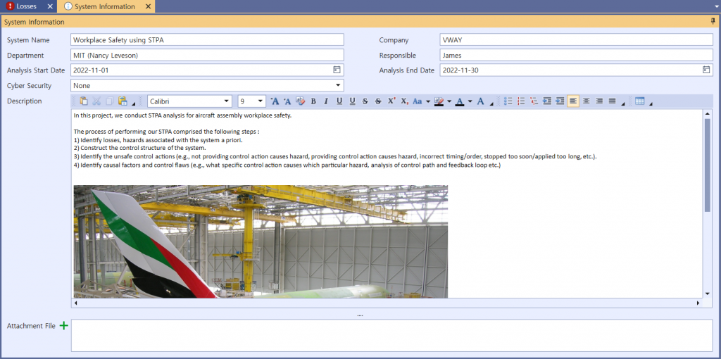
Picture 1. System information of STPA on Aircraft Aseembly Process
1. Identify Losses & Hazards
STPA analysis takes four steps, the first of which is ‘identify Losses & Hazards’. The screen presented below is for identifying Losses.
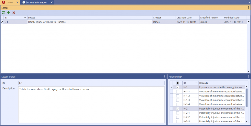
Picture 2. Identifying Losses of Aircraft Assembly Process STPA

Table 1. Losses table of Aircraft Assembly Process STPA
For a system of Aircraft Assembly Process STPA. 5 main Hazards can be identified, three of them involving their own sub-hazards. All Hazards, main or sub, can create a traceable relationship with Losses. The identified hazards are as follows:
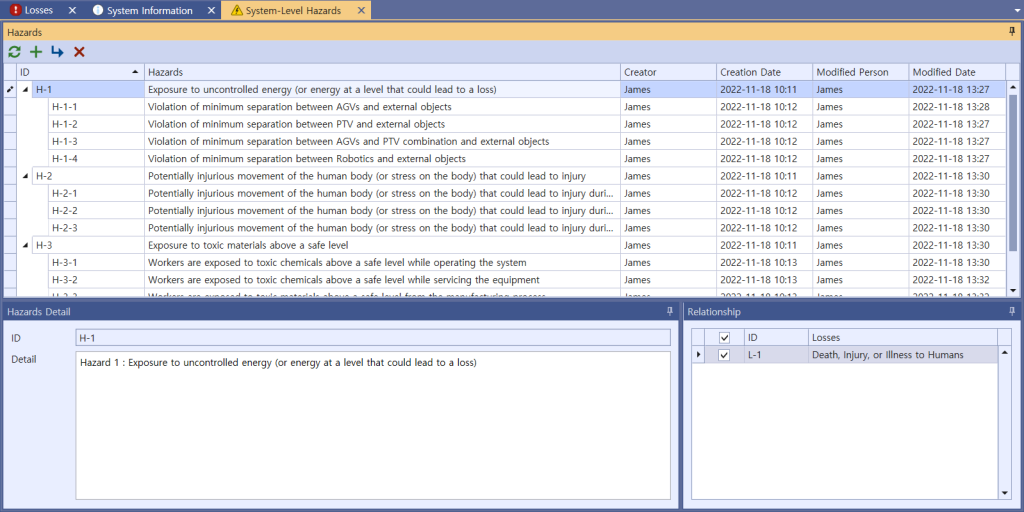
Picture 3. Identifying Hazards of Aircraft Assembly Process STPA
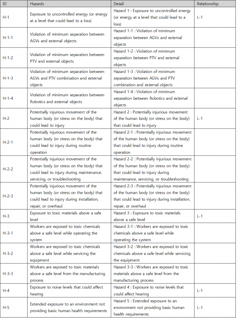
Table 2. Hazards table of Aircraft Assembly Process STPA
2. Control Structure Modeling
The second step out of the four is to build a model of the system called a control structure. A control structure captures functional relationships and interactions by modeling the system as a set of feedback control loops. The control structure usually begins at a very abstract level and then is through iteration refined to capture more detail about the system. This step is essential regardless of whether it concerns safety, security, privacy, or other any other properties. A high-level control structure of the system under analysis is illustrated below. There are several control loops captured in the control structure, such as the control loop between ‘AGV Operator’ and ‘Modules’, between ‘Modules’ and ‘Motors’ and between ‘Motors’ and ‘Wheel Assembly’. The control structure at this abstraction level includes many CAs.
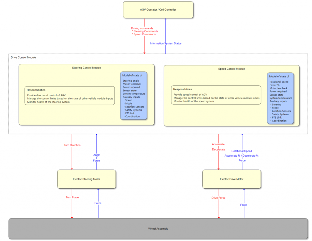
Picture 4. STPA Control Structure Diagram for Aircraft Assembly Process
3. Identify UCA
The third step out of the four identifies Unsafe Control Action (UCA). Accorting to STPA methodology, UCA is created into four types (Not providing causes hazard / Providing causes hazard / Too early, too late, out of order / Stopped too soon, applied too long). The associated UCAs for a Control Actions will be given in the below picture as an example.
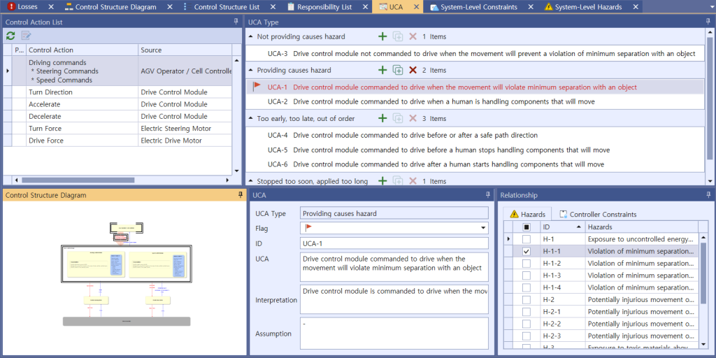
Picture 5. Identifying UCAs of Aircraft Assembly Process STPA
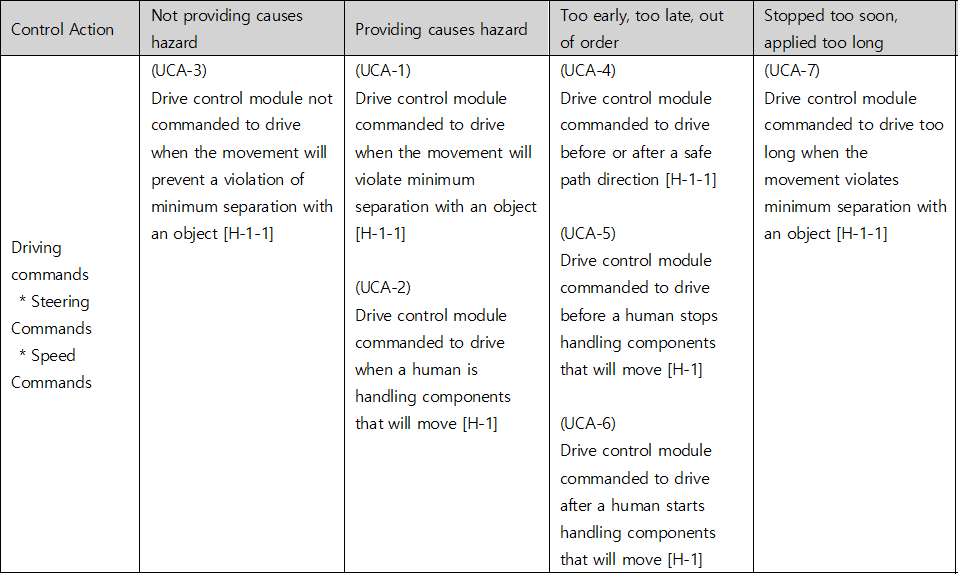
Table 3. UCA table of Aircraft Assembly Process STPA
4. Identify Loss Scenario
Once you have identified an UCA, you should create a scenario that causes it. STPA refers to this as a Loss Scenario and can be written by referring to a Guide Word that causes a Loss Scenario provided by the Handbook. Below are some of the possible Loss Scenario in UCA1 : Drive control module commanded to drive when the movement will violate minimum separation with an object.
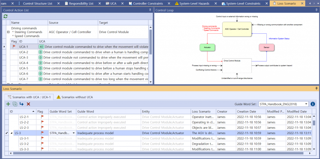
Picture 6. Identifying Loss Scenarios of Aircraft Assembly Process STPA
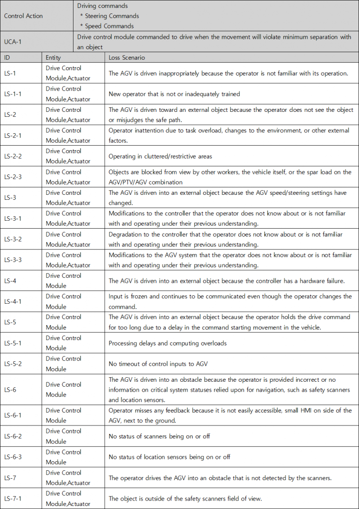
Table 4. Loss Scenario table of Aircraft Assembly Process STPA
Conclusion
The STPA analysis process presented above enabled the visual representation of the whole system, allowing the recording of the traceability of problems, their preceding contexts, and countermeasures against them, thereby contributing to domain knowledge formalization. But, the Aircraft Assembly STPA process above is just some example from the STPA process and the results; the whole mechanics and nature of this will not be always similar. Simultaneously, we have obtained promising results that predict that Aircraft Assembly Process system would remain reliable even if they became more complicated and functionally enhanced.
Nancy G. Leveson & John P. Thomas, “STPA handbook : Chapter 4 : Workplace Safety using STPA”, U.S, 2018



Workplace Safety STPA analysis of Aircraft Assembly Process
Workplace or occupational safety has often focused on the worker’s behavior and not gone beyond that. A system’s approach to workplace safety assumes that human behavior is affected by the system in which it is embedded. The goal is to identify how to design the work environment in order to reduce human error. The application of STPA in this environment is identical to the standard application of STPA on a more technological system. Here, an STPA analysis will be provided about people working with advanced automation. In this case, the major difference between STPA and the standard approach to workplace safety today is that STPA focuses on more than just creating procedures for humans to follow but instead looks at the entire system to identify hazardous scenarios and how to eliminate or reduce them. Because the example below describes a real experimental application of STPA in a manufacturing environment, details about the actual assessment procedure used and the cost can be provided.
Nancy G. Leveson & John P. Thomas, “STPA handbook : Chapter 4 : Workplace Safety using STPA”, U.S, 2018
System Information
The central focus of this analysis step targets safety STPA analysis of aircraft assembly process. The following picture is the system information screen where the abstract for the analysis will be described in general.
Picture 1. System information of STPA on Aircraft Aseembly Process
1. Identify Losses & Hazards
STPA analysis takes four steps, the first of which is ‘identify Losses & Hazards’. The screen presented below is for identifying Losses.
Picture 2. Identifying Losses of Aircraft Assembly Process STPA
Table 1. Losses table of Aircraft Assembly Process STPA
For a system of Aircraft Assembly Process STPA. 5 main Hazards can be identified, three of them involving their own sub-hazards. All Hazards, main or sub, can create a traceable relationship with Losses. The identified hazards are as follows:
Picture 3. Identifying Hazards of Aircraft Assembly Process STPA
Table 2. Hazards table of Aircraft Assembly Process STPA
2. Control Structure Modeling
The second step out of the four is to build a model of the system called a control structure. A control structure captures functional relationships and interactions by modeling the system as a set of feedback control loops. The control structure usually begins at a very abstract level and then is through iteration refined to capture more detail about the system. This step is essential regardless of whether it concerns safety, security, privacy, or other any other properties. A high-level control structure of the system under analysis is illustrated below. There are several control loops captured in the control structure, such as the control loop between ‘AGV Operator’ and ‘Modules’, between ‘Modules’ and ‘Motors’ and between ‘Motors’ and ‘Wheel Assembly’. The control structure at this abstraction level includes many CAs.
Picture 4. STPA Control Structure Diagram for Aircraft Assembly Process
3. Identify UCA
The third step out of the four identifies Unsafe Control Action (UCA). Accorting to STPA methodology, UCA is created into four types (Not providing causes hazard / Providing causes hazard / Too early, too late, out of order / Stopped too soon, applied too long). The associated UCAs for a Control Actions will be given in the below picture as an example.
Picture 5. Identifying UCAs of Aircraft Assembly Process STPA
Table 3. UCA table of Aircraft Assembly Process STPA
4. Identify Loss Scenario
Once you have identified an UCA, you should create a scenario that causes it. STPA refers to this as a Loss Scenario and can be written by referring to a Guide Word that causes a Loss Scenario provided by the Handbook. Below are some of the possible Loss Scenario in UCA1 : Drive control module commanded to drive when the movement will violate minimum separation with an object.
Picture 6. Identifying Loss Scenarios of Aircraft Assembly Process STPA
Table 4. Loss Scenario table of Aircraft Assembly Process STPA
Conclusion
The STPA analysis process presented above enabled the visual representation of the whole system, allowing the recording of the traceability of problems, their preceding contexts, and countermeasures against them, thereby contributing to domain knowledge formalization. But, the Aircraft Assembly STPA process above is just some example from the STPA process and the results; the whole mechanics and nature of this will not be always similar. Simultaneously, we have obtained promising results that predict that Aircraft Assembly Process system would remain reliable even if they became more complicated and functionally enhanced.
Nancy G. Leveson & John P. Thomas, “STPA handbook : Chapter 4 : Workplace Safety using STPA”, U.S, 2018