Urban air mobility (UAM) for passenger carrying operations promises to revolutionize transportation by potentially reducing urban congestion and passenger delay, enabling flexible response to changing transportation needs, and creating new market opportunities. Vehicles capable of vertical takeoff and landing are envisioned to operate from sites that are capable of loading and unloading passengers and handling multiple aircraft. These operations will also require enhanced air traffic management and conflict detection and avoidance capabilities in order to ensure safe, scalable operations. The UAM community, which includes many new entrants, faces a regulatory environment in flux. The community is presently discussing several options for certifying electric vertical takeoff and landing (eVTOL) aircraft in the USA. However, regardless of authentication, some safety principles and technologies are fundamental. The design of a secure UAM operating system begins with a system safety analysis. Use the example to show how to perform a safety analysis of the UAM system with STPA.
1. System Information
STPA Anlaysis target is a eVTOL of UAM. Following Picture is eVTOL’s system information.
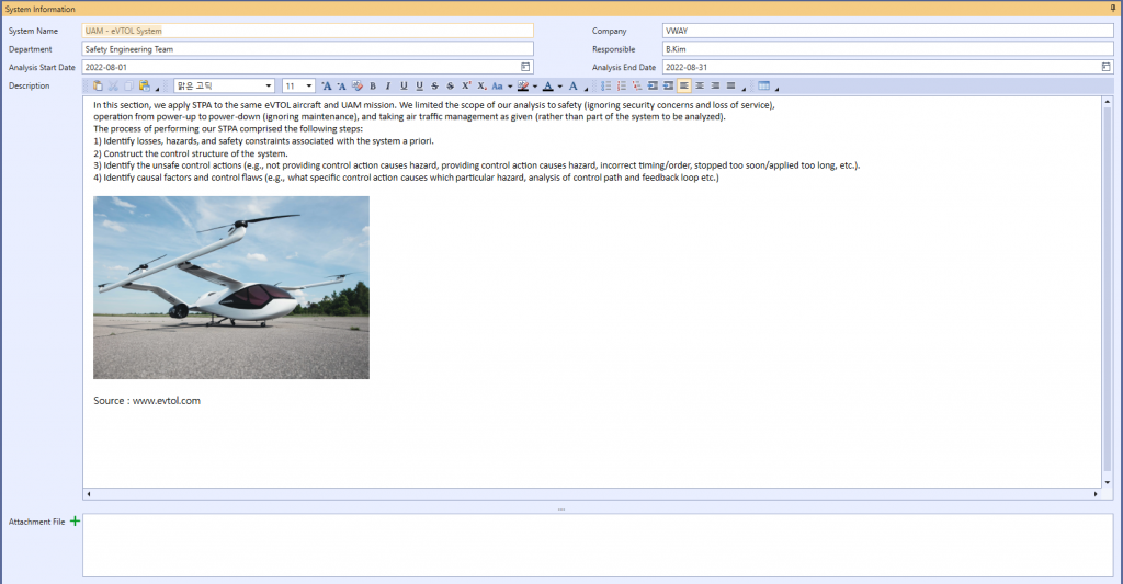
Picture 1. eVTOL's system information
2. Identify Losses & Hazards
The possible losses in eVTOL are identified as follows:
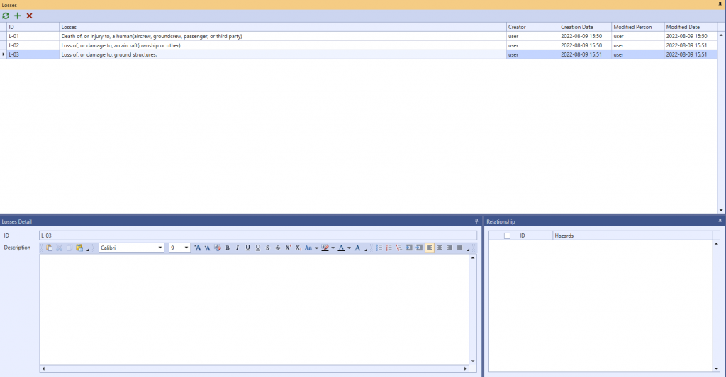
Picture 2. eVTOL's losses
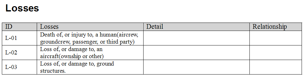
Table 1. eVTOL's losses table
For systems in eVTOL, 9 hazards can be identified. Among the Hazards, Hazards factors were divided in sub-hazards according to the case where a clearer expression was needed. The identified hazards are as follows:
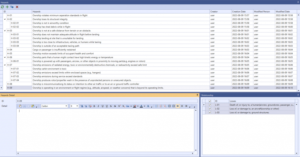
Picture 3. eVTOL's hazards
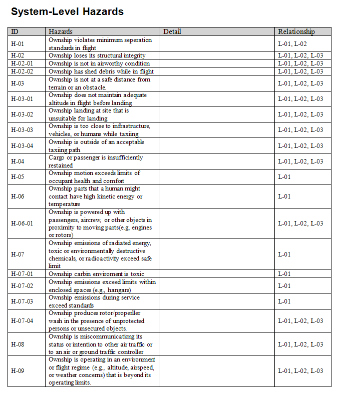
Table 2. eVTOL's hazards table
3. Identify Constraints
These hazards can be used to derive safety constraints. Simply by reversing the conditions of the hazardss. Examples of safety restrictions are as follows:
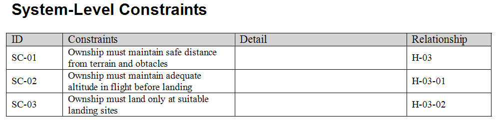
Table 3. Constraints table
4. Control Structure Modeling
A consideration of the vehicle, environment, operational procedures and human interaction paths is fundamental to being able to construct a model of the system’s control structure, including its myriad feedback mechanisms. A systematic consideration of each control variable helps to define its impact on all potential hazards. In STPA, control structures are comprised of controllers, control actions, and feedback. Controllers, which might be human beings, subsystems, or teams of these, are depicted as rectangles. Control actions that controllers make and feedback that they receive are depicted using arrows. In this analysis, we defined the hierarchical control structure shown in below picture. As is usual in STPA, the highest-level controllers appear at the top of the diagram and the lowest-level controllers at the bottom. Text accompanying the figure elaborates on the controllers, control actions, feedback, and the controllers’ responsibilities.
For example:
Thrust setting control action given to the rotors / propellers / motors. While the exact nature of the aircraft’s propulsion and lift mechanisms have yet to be decided, there will be rotors or propellers and their associated motors. In order to make the ownship aircraft fly per the flight control inputs (if being hand-flown) or the given trajectory (otherwise), the flight controller commands the motors and rotors or propellers to produce the thrust needed to accomplish that.
In defining this control structure, we chose a level of abstraction suitable for an analysis that was (a) performed early in the development life-cycle of the eVTOL and (b) focused on the aircraft rather than for managing such air traffic (e.g.,onboard functions like collision avoidance are considered, while offboard functions like separation management are abstracted). For example, because system design is as yet immature, we abstracted all of the sensors, hardware, and software responsible for turning pilot or automatic navigation commands into flight surface control actions into a single flight controller. Because we are still exploring options related to the number and placement of rotors or propellers, whether these are fixed or can tilt from vertical to horizontal, whether the aircraft has fixed wings, etc., we abstracted those elements into the controllers labeled rotors / propellers / motors, control effectors, and transition mechanism in below picture. Later in the system lifecycle, after related design decisions have been made, we would revisit the analysis and refine the level of abstraction.
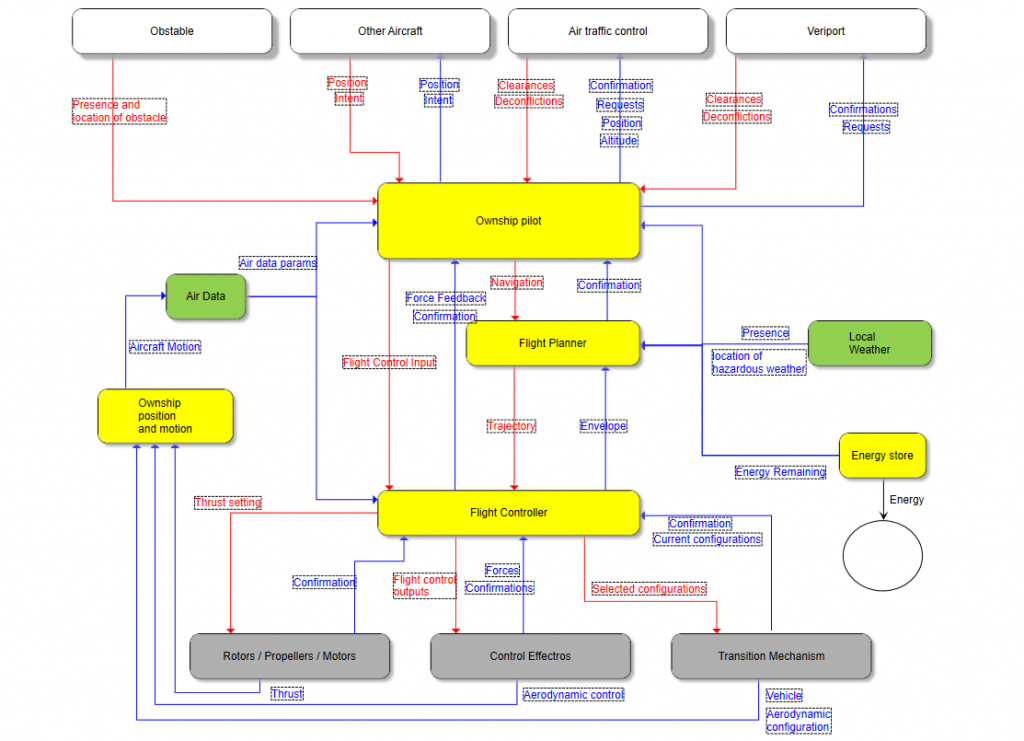
Picture 4. STPA Control Structure Diagram for UAM aircraft
5. Identify UCA
The following steps identify the Unsafe Control Action (UCA). Based on STPA theory, UCA is created according to four types (Not Provided, Provided, Provided Too Soon/Late, Provided Too Long/Short). Below, only a few of the many CAs want to identify UCA. The figures below are picture and table that identify the occurrence of UCA in terms of the Flight Controller controlling Thrust Setting.
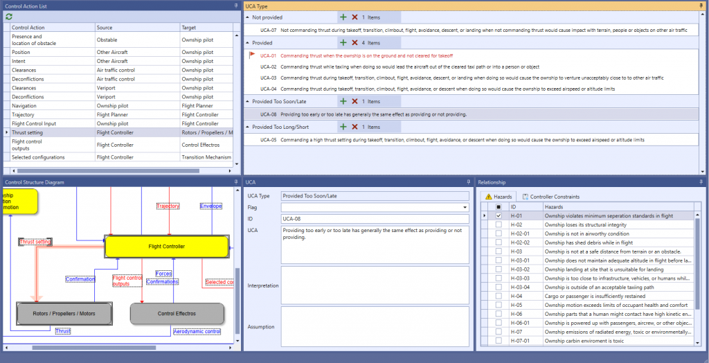
Picture 5. Thrust setting UCA
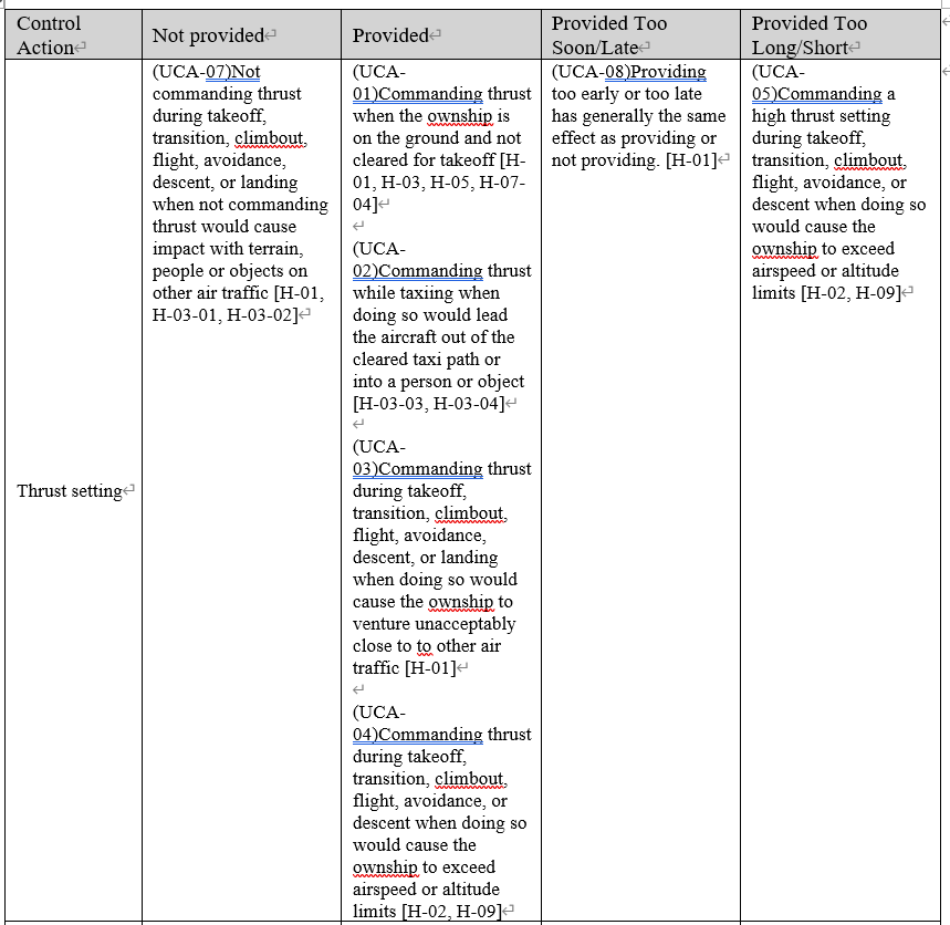
Table 4. Thrust setting's UCA table
6. Identify Loss Scenario
Once you have identified a UCA, you must create a scenario that causes it. STPA refers to this as a loss scenario and can be written by referring to a guide word, etc. that causes a loss scenario provided by the Handbook. Below are some of the possible loss scenario in UCA3-commanding trust dumping takeoff, transition, climbout, flight, avoidance, descent, or landing when doing so would cause the outsourcing to venture unacceptably close to other air traffic.
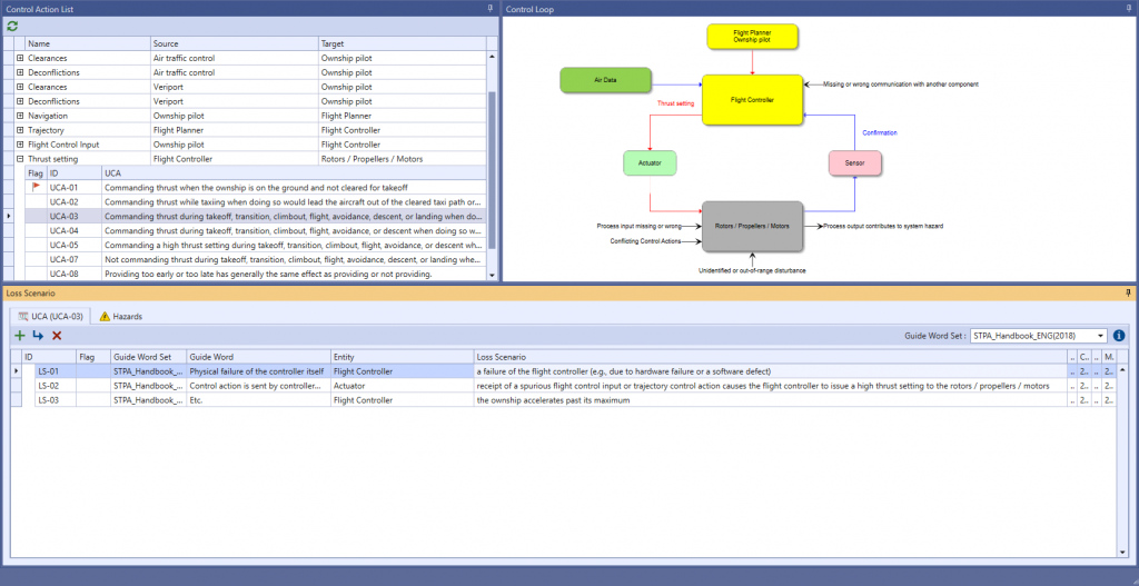
Picture 6. Loss Scenario
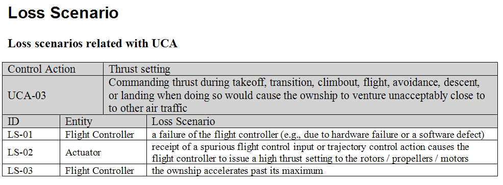
Table 5. Loss Scenario table
7. Conclusion
We are trying to demonstrate to regulators that UAM operations using eVTOL aircraft are at a guaranteed level. This requires compliance with the basic principles of system safety, which are necessary to access the national public system. To demonstrate that the system meets requirements (e.g. certification criteria) and mitigates the following, the applicant must consider both vehicle and operation to carry out hazardous operations identified to the hazard level. This requires a meaningful safety assessment, and this study performs a risk assessment. These techniques were evaluated and used for eVTOL vehicle UAM operation using two techniques: Functional Risk Assessment (FHA) and System Theoretical Process Analysis (STPA). Two risk analysis techniques enable risk assessment with multiple mitigation strategies in the context of a single risk. It also enabled the creation of vehicle type certification, operation and crew training requirements, including: Working with both new OEMs and regulators can help validate the above approach, and these analyses are now being formulated.
Mallory S. Graydon and Natasha A. Neogi and Kimberly S. Wasson, “Guidance for Designing Safety into Urban Air Mobility : Hazard Analysis Techniques”, USA, 2020



Urban air mobility (UAM) for passenger carrying operations promises to revolutionize transportation by potentially reducing urban congestion and passenger delay, enabling flexible response to changing transportation needs, and creating new market opportunities. Vehicles capable of vertical takeoff and landing are envisioned to operate from sites that are capable of loading and unloading passengers and handling multiple aircraft. These operations will also require enhanced air traffic management and conflict detection and avoidance capabilities in order to ensure safe, scalable operations. The UAM community, which includes many new entrants, faces a regulatory environment in flux. The community is presently discussing several options for certifying electric vertical takeoff and landing (eVTOL) aircraft in the USA. However, regardless of authentication, some safety principles and technologies are fundamental. The design of a secure UAM operating system begins with a system safety analysis. Use the example to show how to perform a safety analysis of the UAM system with STPA.
1. System Information
STPA Anlaysis target is a eVTOL of UAM. Following Picture is eVTOL’s system information.
Picture 1. eVTOL's system information
2. Identify Losses & Hazards
The possible losses in eVTOL are identified as follows:
Picture 2. eVTOL's losses
Table 1. eVTOL's losses table
For systems in eVTOL, 9 hazards can be identified. Among the Hazards, Hazards factors were divided in sub-hazards according to the case where a clearer expression was needed. The identified hazards are as follows:
Picture 3. eVTOL's hazards
Table 2. eVTOL's hazards table
3. Identify Constraints
These hazards can be used to derive safety constraints. Simply by reversing the conditions of the hazardss. Examples of safety restrictions are as follows:
Table 3. Constraints table
4. Control Structure Modeling
A consideration of the vehicle, environment, operational procedures and human interaction paths is fundamental to being able to construct a model of the system’s control structure, including its myriad feedback mechanisms. A systematic consideration of each control variable helps to define its impact on all potential hazards. In STPA, control structures are comprised of controllers, control actions, and feedback. Controllers, which might be human beings, subsystems, or teams of these, are depicted as rectangles. Control actions that controllers make and feedback that they receive are depicted using arrows. In this analysis, we defined the hierarchical control structure shown in below picture. As is usual in STPA, the highest-level controllers appear at the top of the diagram and the lowest-level controllers at the bottom. Text accompanying the figure elaborates on the controllers, control actions, feedback, and the controllers’ responsibilities.
For example:
Thrust setting control action given to the rotors / propellers / motors. While the exact nature of the aircraft’s propulsion and lift mechanisms have yet to be decided, there will be rotors or propellers and their associated motors. In order to make the ownship aircraft fly per the flight control inputs (if being hand-flown) or the given trajectory (otherwise), the flight controller commands the motors and rotors or propellers to produce the thrust needed to accomplish that.
In defining this control structure, we chose a level of abstraction suitable for an analysis that was (a) performed early in the development life-cycle of the eVTOL and (b) focused on the aircraft rather than for managing such air traffic (e.g.,onboard functions like collision avoidance are considered, while offboard functions like separation management are abstracted). For example, because system design is as yet immature, we abstracted all of the sensors, hardware, and software responsible for turning pilot or automatic navigation commands into flight surface control actions into a single flight controller. Because we are still exploring options related to the number and placement of rotors or propellers, whether these are fixed or can tilt from vertical to horizontal, whether the aircraft has fixed wings, etc., we abstracted those elements into the controllers labeled rotors / propellers / motors, control effectors, and transition mechanism in below picture. Later in the system lifecycle, after related design decisions have been made, we would revisit the analysis and refine the level of abstraction.
Picture 4. STPA Control Structure Diagram for UAM aircraft
5. Identify UCA
The following steps identify the Unsafe Control Action (UCA). Based on STPA theory, UCA is created according to four types (Not Provided, Provided, Provided Too Soon/Late, Provided Too Long/Short). Below, only a few of the many CAs want to identify UCA. The figures below are picture and table that identify the occurrence of UCA in terms of the Flight Controller controlling Thrust Setting.
Picture 5. Thrust setting UCA
Table 4. Thrust setting's UCA table
6. Identify Loss Scenario
Once you have identified a UCA, you must create a scenario that causes it. STPA refers to this as a loss scenario and can be written by referring to a guide word, etc. that causes a loss scenario provided by the Handbook. Below are some of the possible loss scenario in UCA3-commanding trust dumping takeoff, transition, climbout, flight, avoidance, descent, or landing when doing so would cause the outsourcing to venture unacceptably close to other air traffic.
Picture 6. Loss Scenario
Table 5. Loss Scenario table
7. Conclusion
We are trying to demonstrate to regulators that UAM operations using eVTOL aircraft are at a guaranteed level. This requires compliance with the basic principles of system safety, which are necessary to access the national public system. To demonstrate that the system meets requirements (e.g. certification criteria) and mitigates the following, the applicant must consider both vehicle and operation to carry out hazardous operations identified to the hazard level. This requires a meaningful safety assessment, and this study performs a risk assessment. These techniques were evaluated and used for eVTOL vehicle UAM operation using two techniques: Functional Risk Assessment (FHA) and System Theoretical Process Analysis (STPA). Two risk analysis techniques enable risk assessment with multiple mitigation strategies in the context of a single risk. It also enabled the creation of vehicle type certification, operation and crew training requirements, including: Working with both new OEMs and regulators can help validate the above approach, and these analyses are now being formulated.
Mallory S. Graydon and Natasha A. Neogi and Kimberly S. Wasson, “Guidance for Designing Safety into Urban Air Mobility : Hazard Analysis Techniques”, USA, 2020