The Engine Stop & Start system is a system that helps the engine run again when the car is stationary and when the pedal is pressed. Depending on the driving environment, ESS systems can provide benefits such as fuel efficiency savings and engine life management when shutdown times are high. Now we are going to start STPA analysis.
1. Identify Losses and System-Level Hazards
The losses table on ESS systems are as follows: You can check the below table as well as the loss screen identified in the VisualPro SA-STPA tool. Losses associated with the automotive industry do not deviate significantly from the framework of the four losses below. The same applies to other vehicle systems.
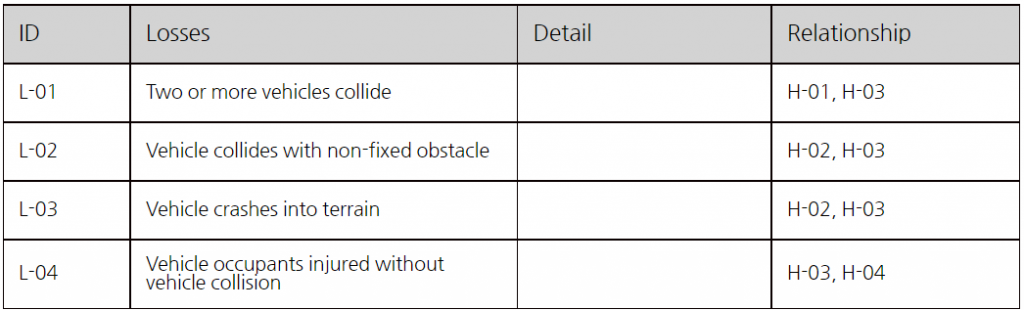
Table 1. ESS System's Losses
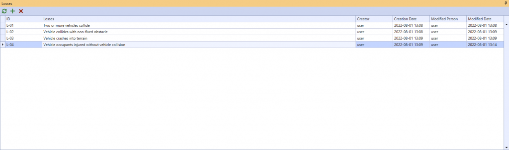
Picture 1. EPS's losses screen on VisualPro SA
Now it's time to identify hazards that could cause losses. Identify hazards and specify associations with losses. Identified hazards and tables & screen are shown below.
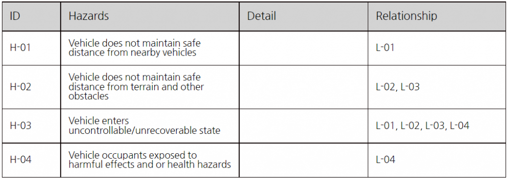
Table 2. ESS System's Hazards
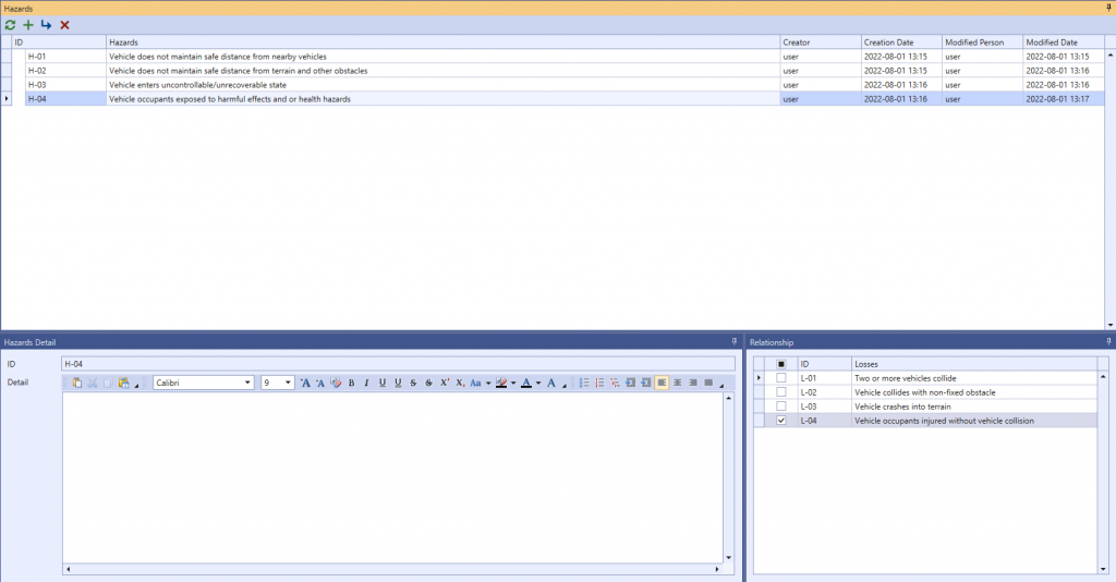
Picture 2. ESS System's Hazard on VisualPro SA
2. Control Structure Modeling
This is the step to configure the overall Control Structure modeling of ESS systems. The components that make up the ESS system can be viewed as the Driver, Auto Engine Stop-Start Module, Inertial Unit, Braking System, Propulsion System, Environment. The CS modeling of the completed ESS system is as follows.
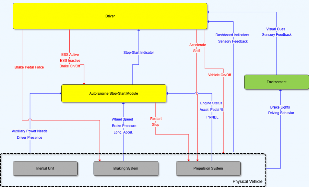 Picture 3. ESS System's Control Structure Model
3. Identify UCA(Unsafe Control Action)
The UCA identifiable in the ESS is shown in the table below. The UCA was identified as the control action target for Restart and Stop directly related to the ESS system.
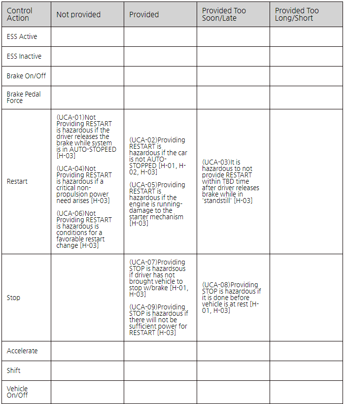
Table 3. ESS System UCA
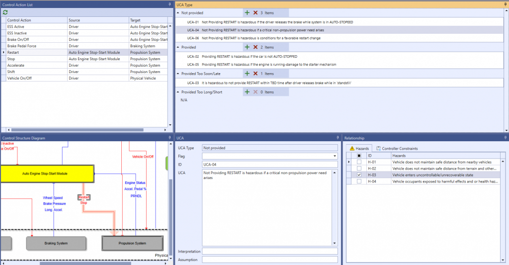
Picture 4. Identify UCA on VisualPro SA
4. Identify Controller Constraints
Once the Unsafe Control Action (UCA) has been defined, you can define the constraints under each UCA to prevent UCA. The controller constraints that can be defined in the ESS system are as follows:
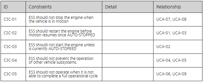
Table 4. ESS System Controller Constraints
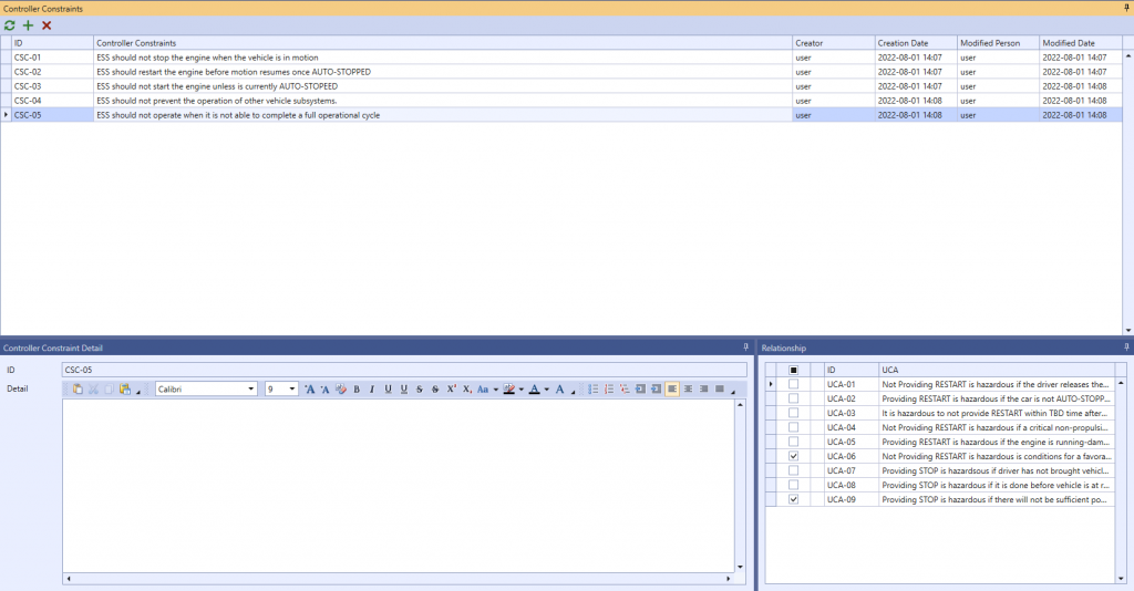
Picture 4. ESS System's Controller Constraints on VisualPro SA
5. Identify Loss Scenarios
After identifying UCA, create a loss scenario that can cause each UCA. STPA provides a guide word for reference when writing a loss scenario. VisualPro SA – The STPA tool also provides a standard STPA Handbook 2018 Guide Word.
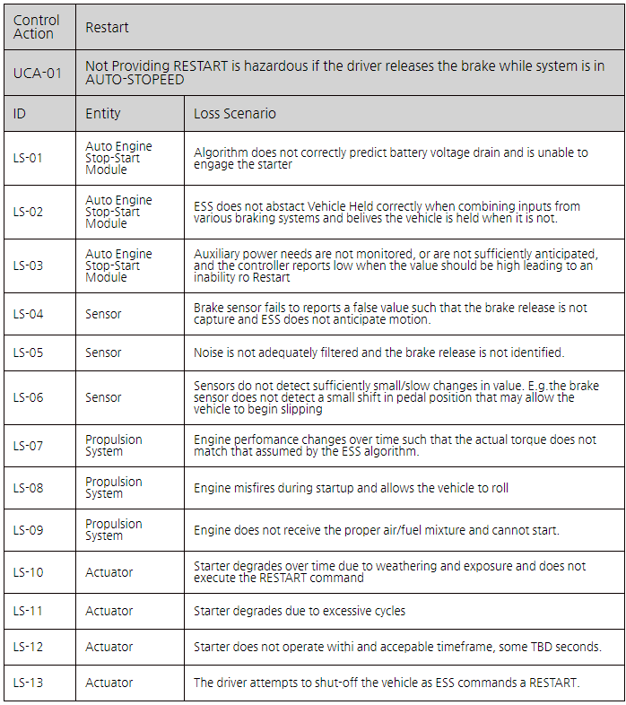
Table 5. UCA-01's Loss Scenarios
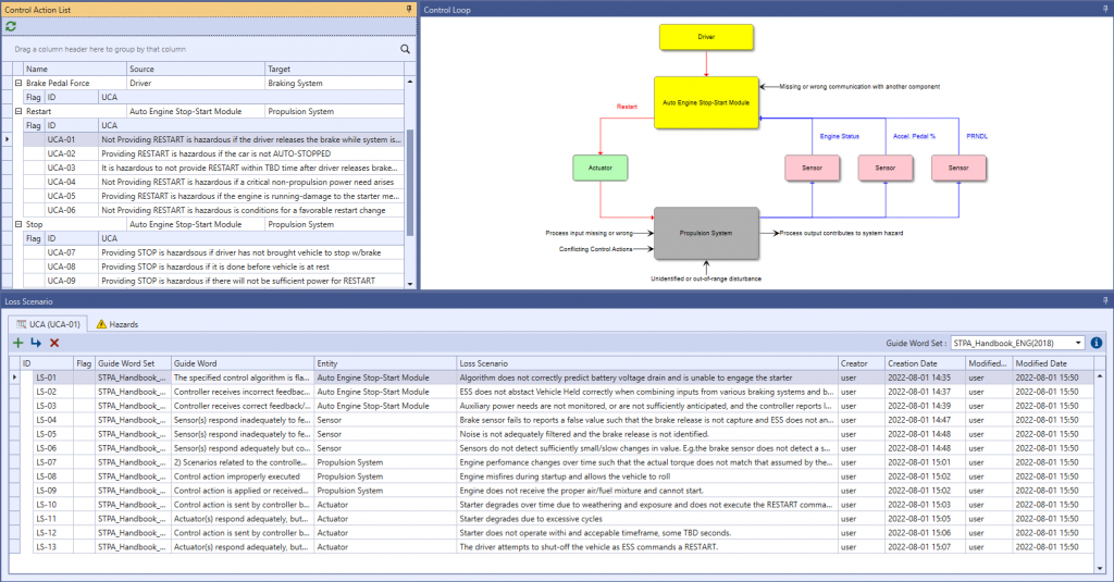
Picture 6. UCA-01's Loss Scenarios on VisualPro SA
Additional countermeasures (requirements) can be prepared according to the loss scenario. This is a traceability view of everything from losses to countermeasures.
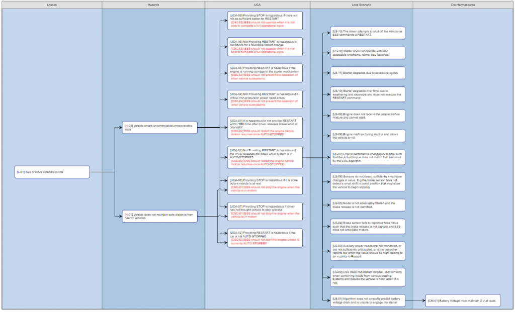
Picture 7. L-01 Two or More vehicles collide
Matthew Seth Placke, "Application of STPA to the integration of multiple control systems : A case study and new approach", 2012



The Engine Stop & Start system is a system that helps the engine run again when the car is stationary and when the pedal is pressed. Depending on the driving environment, ESS systems can provide benefits such as fuel efficiency savings and engine life management when shutdown times are high. Now we are going to start STPA analysis.
1. Identify Losses and System-Level Hazards
The losses table on ESS systems are as follows: You can check the below table as well as the loss screen identified in the VisualPro SA-STPA tool. Losses associated with the automotive industry do not deviate significantly from the framework of the four losses below. The same applies to other vehicle systems.
Table 1. ESS System's Losses
Picture 1. EPS's losses screen on VisualPro SA
Now it's time to identify hazards that could cause losses. Identify hazards and specify associations with losses. Identified hazards and tables & screen are shown below.
Table 2. ESS System's Hazards
Picture 2. ESS System's Hazard on VisualPro SA
2. Control Structure Modeling
This is the step to configure the overall Control Structure modeling of ESS systems. The components that make up the ESS system can be viewed as the Driver, Auto Engine Stop-Start Module, Inertial Unit, Braking System, Propulsion System, Environment. The CS modeling of the completed ESS system is as follows.
3. Identify UCA(Unsafe Control Action)
The UCA identifiable in the ESS is shown in the table below. The UCA was identified as the control action target for Restart and Stop directly related to the ESS system.
Table 3. ESS System UCA
Picture 4. Identify UCA on VisualPro SA
4. Identify Controller Constraints
Once the Unsafe Control Action (UCA) has been defined, you can define the constraints under each UCA to prevent UCA. The controller constraints that can be defined in the ESS system are as follows:
Table 4. ESS System Controller Constraints
Picture 4. ESS System's Controller Constraints on VisualPro SA
5. Identify Loss Scenarios
After identifying UCA, create a loss scenario that can cause each UCA. STPA provides a guide word for reference when writing a loss scenario. VisualPro SA – The STPA tool also provides a standard STPA Handbook 2018 Guide Word.
Table 5. UCA-01's Loss Scenarios
Picture 6. UCA-01's Loss Scenarios on VisualPro SA
Additional countermeasures (requirements) can be prepared according to the loss scenario. This is a traceability view of everything from losses to countermeasures.
Picture 7. L-01 Two or More vehicles collide
Matthew Seth Placke, "Application of STPA to the integration of multiple control systems : A case study and new approach", 2012