In our previous VisualPro Tech Insight, we demonstrated how to seamlessly transition into an FMEA analysis based on the results of an STPA (Systems Theoretic Process Analysis) that identified hidden threats within a semiconductor fab.
This time, we will demonstrate how to construct an FTA structure based on those FMEA analysis results, as well as how to build an initial FTA structure using nothing more than an image of a system architecture.
1. Constructing FTA from FMEA Data
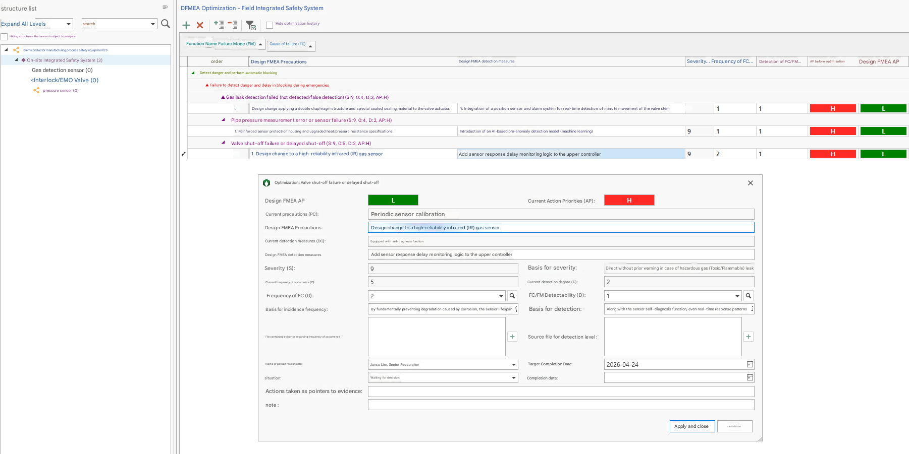
First, we will take the results of the "semiconductor manufacturing process safety equipment" analysis—which previously progressed from STPA to FMEA—and construct it directly into an FTA structure.
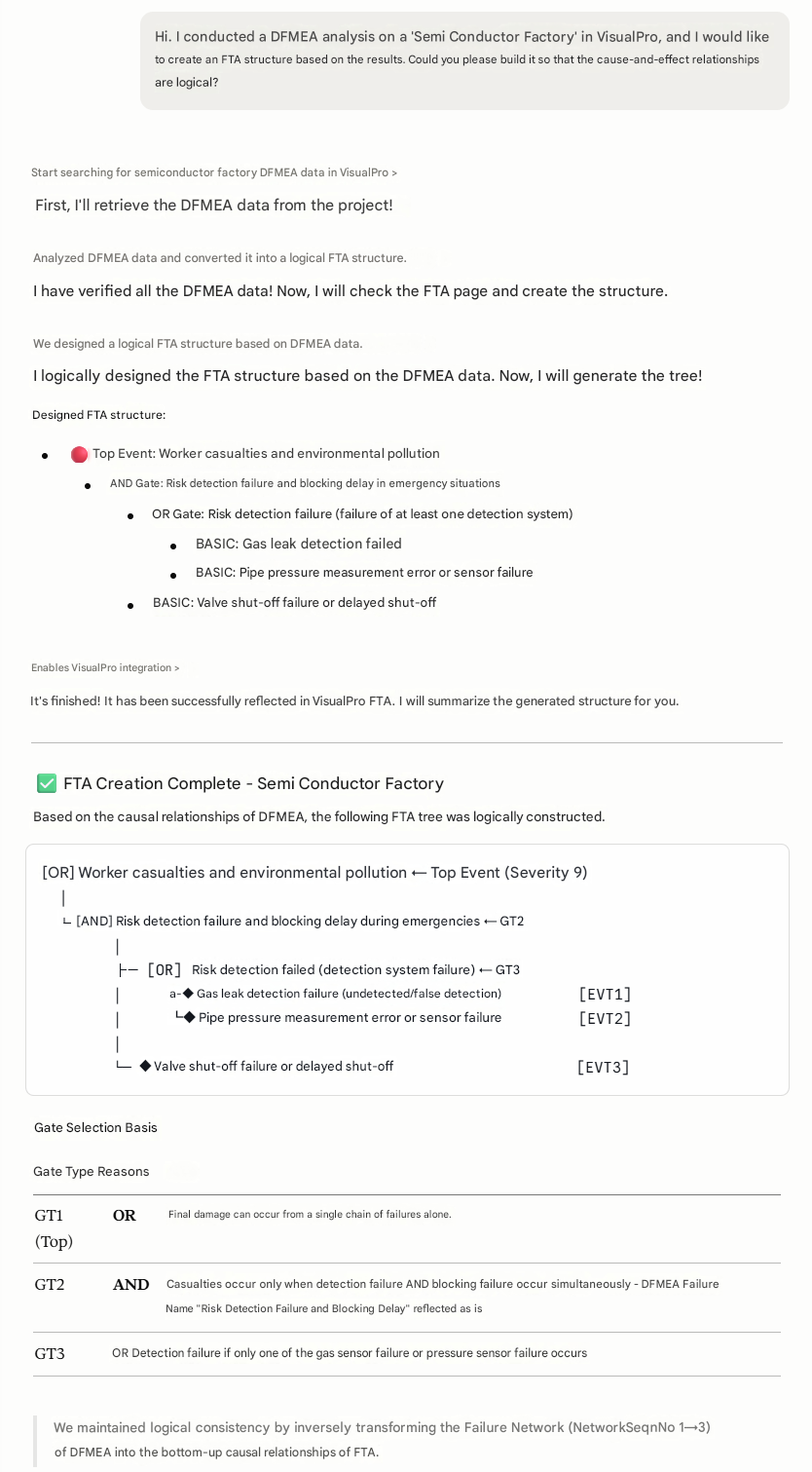
We will utilize the Sonnet 4.6 adaptive model on Claude Desktop for this process.
The FTA structure is built based on the currently completed FMEA.
We established the tree structure of the FTA using a bottom-up approach, based entirely on the causal relationships identified in the FMEA analysis.
You can see that the conversion from FMEA to FTA within VisualPro is executed effortlessly with a single command to the AI, bypassing any cumbersome procedures.
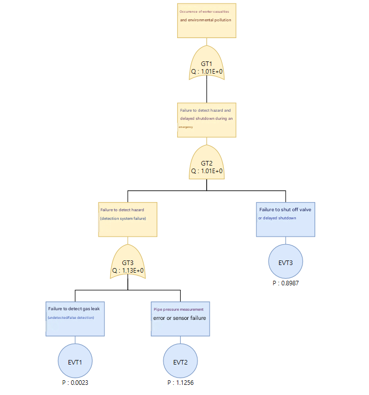
Recalling the previous conversion of the VisualPro STPA analysis into FMEA, we can see a continuous, streamlined conversion flow: from STPA to FMEA, and then from FMEA to FTA.
2. Constructing FTA from System Architecture Images
Next, we will proceed with constructing an FTA using only an image of the system architecture. This is possible because recent AI models feature advanced vision capabilities that allow them to recognize and interpret images.
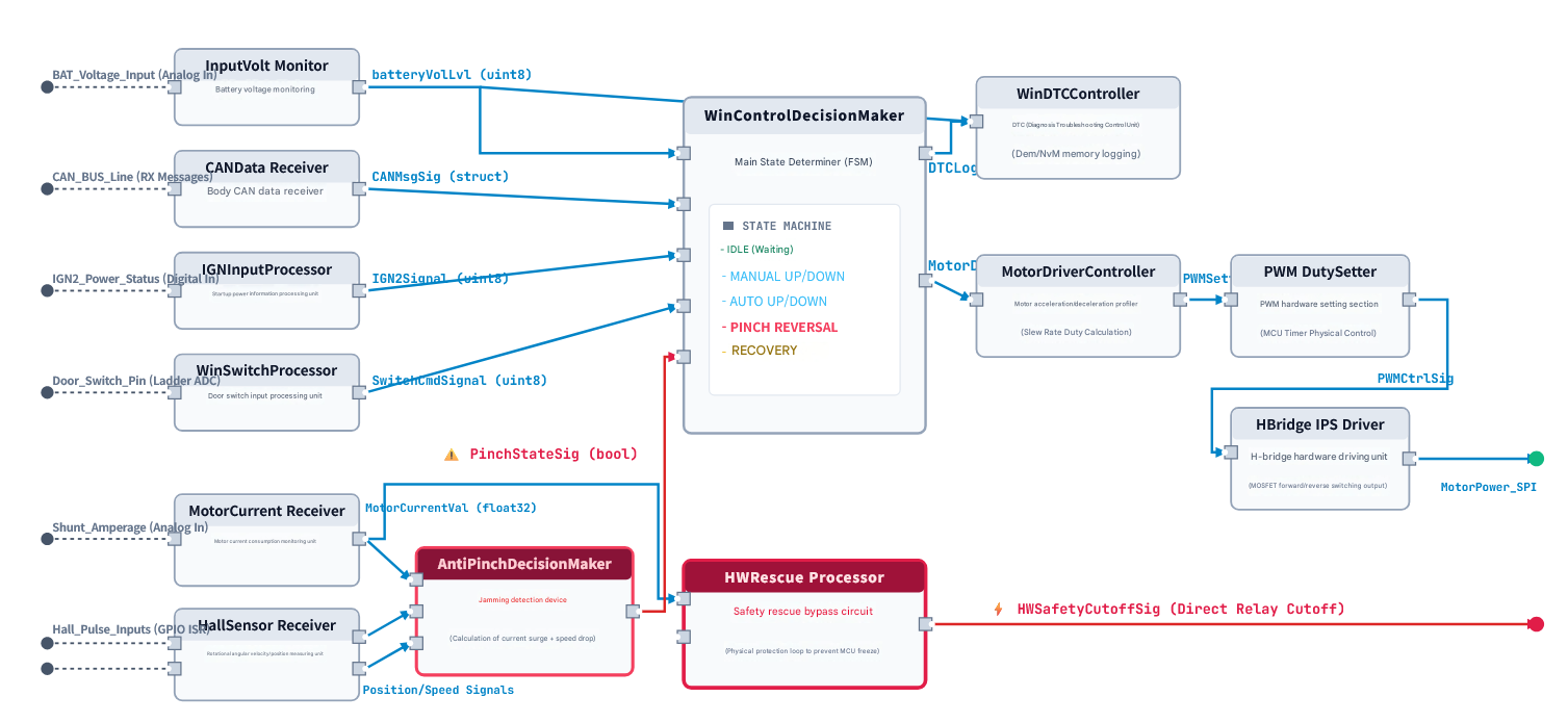
For this analysis, we will build the FTA using a system architecture of a virtual "Window Lift Motor".
Similarly, we will utilize Claude Desktop's Sonnet 4.6 adaptive model.
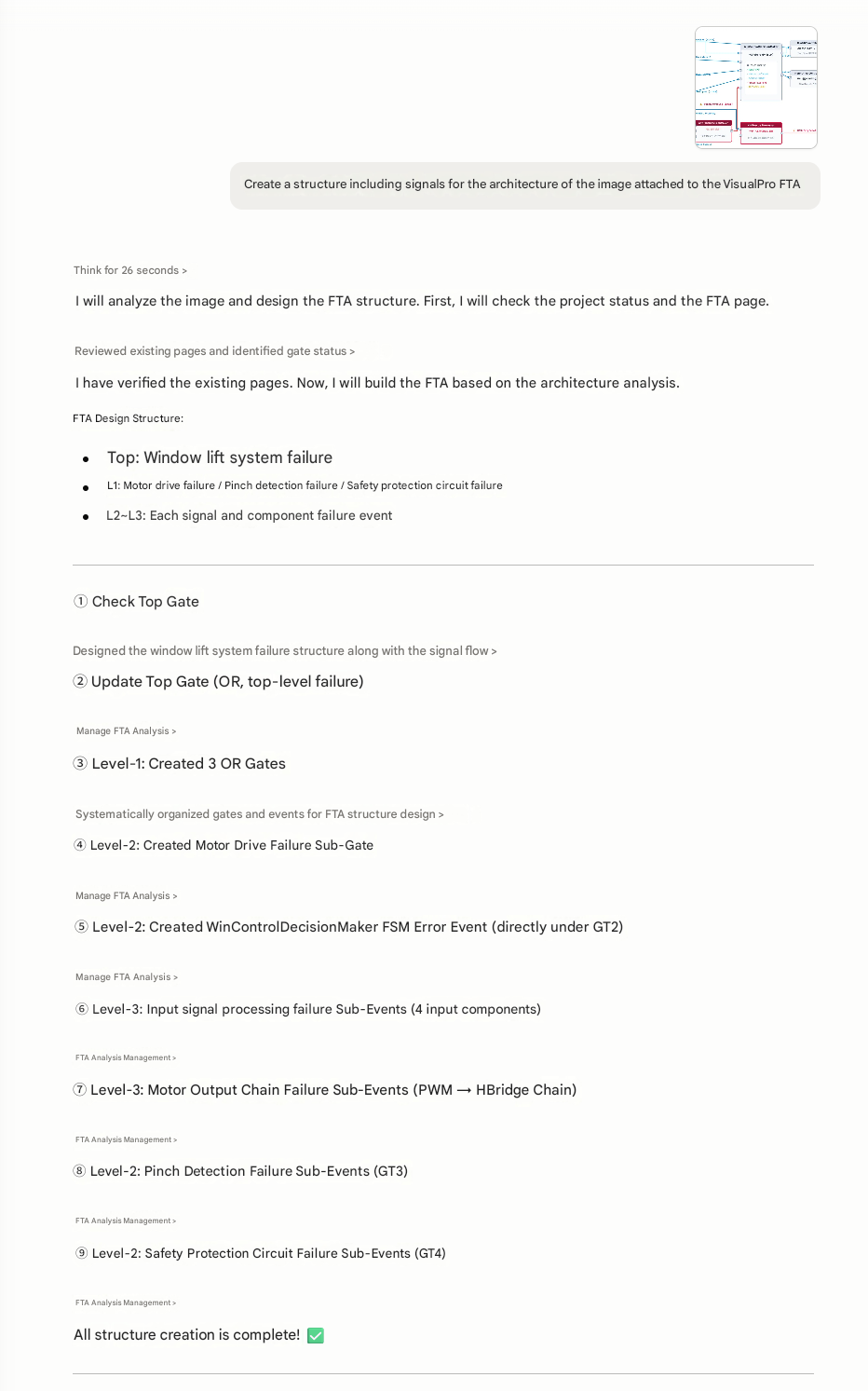
The prompt can be provided simply, as illustrated in the figure.
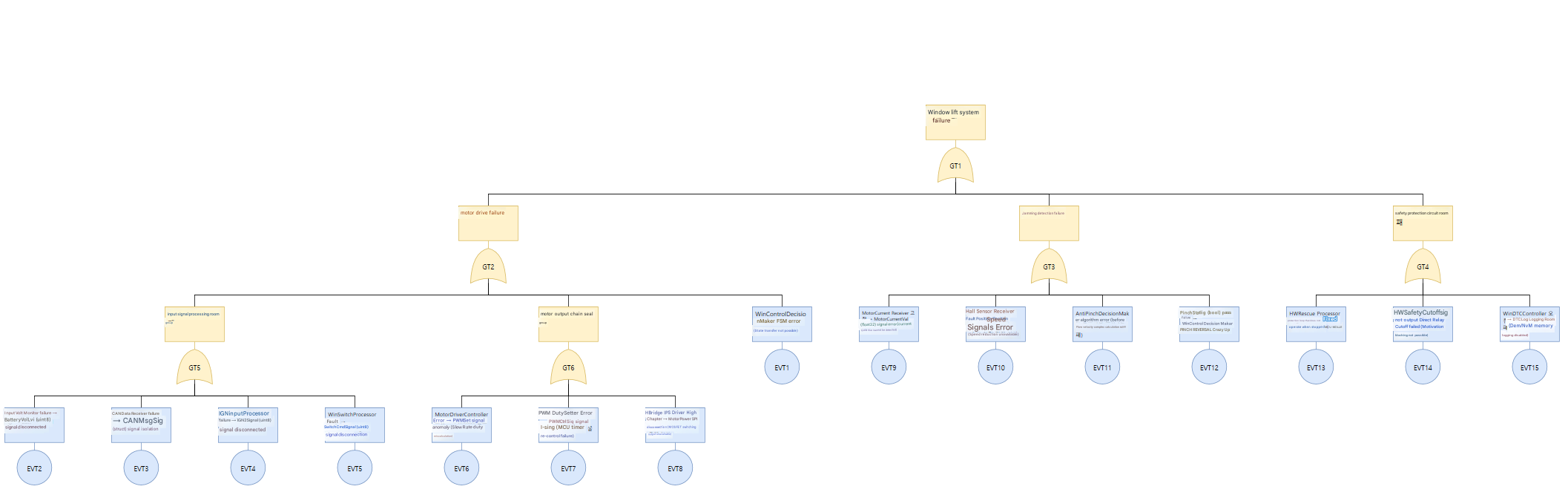
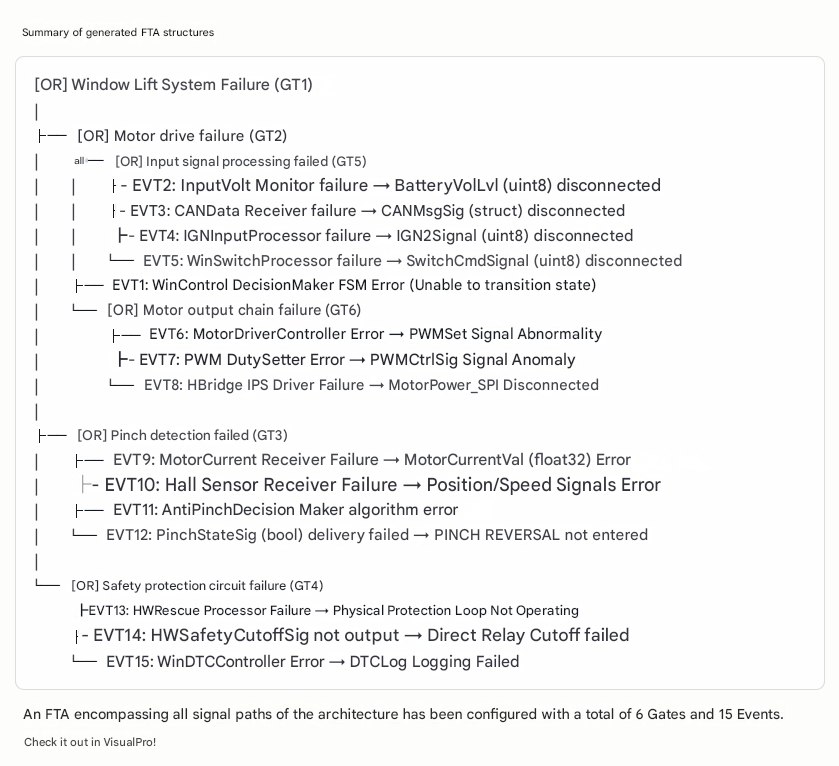
The FTA structure was successfully constructed based solely on the architecture image.
Conclusion
In this way, VisualPro leverages AI features to assist analysts in setting up initial analysis environments much more easily, a process that is traditionally cumbersome and difficult.
※ Note: This analysis was conducted using the AI model connection feature via MCP within the VisualPro FTA environment, and was written in connection with existing analyses.


In our previous VisualPro Tech Insight, we demonstrated how to seamlessly transition into an FMEA analysis based on the results of an STPA (Systems Theoretic Process Analysis) that identified hidden threats within a semiconductor fab.
This time, we will demonstrate how to construct an FTA structure based on those FMEA analysis results, as well as how to build an initial FTA structure using nothing more than an image of a system architecture.
1. Constructing FTA from FMEA Data
First, we will take the results of the "semiconductor manufacturing process safety equipment" analysis—which previously progressed from STPA to FMEA—and construct it directly into an FTA structure.
We will utilize the Sonnet 4.6 adaptive model on Claude Desktop for this process.
The FTA structure is built based on the currently completed FMEA.
We established the tree structure of the FTA using a bottom-up approach, based entirely on the causal relationships identified in the FMEA analysis.
You can see that the conversion from FMEA to FTA within VisualPro is executed effortlessly with a single command to the AI, bypassing any cumbersome procedures.
Recalling the previous conversion of the VisualPro STPA analysis into FMEA, we can see a continuous, streamlined conversion flow: from STPA to FMEA, and then from FMEA to FTA.
2. Constructing FTA from System Architecture Images
Next, we will proceed with constructing an FTA using only an image of the system architecture. This is possible because recent AI models feature advanced vision capabilities that allow them to recognize and interpret images.
For this analysis, we will build the FTA using a system architecture of a virtual "Window Lift Motor".
Similarly, we will utilize Claude Desktop's Sonnet 4.6 adaptive model.
The prompt can be provided simply, as illustrated in the figure.
The FTA structure was successfully constructed based solely on the architecture image.
We can confirm that the details of the events and gates have been mapped and inserted with logical accuracy.
Conclusion
In this way, VisualPro leverages AI features to assist analysts in setting up initial analysis environments much more easily, a process that is traditionally cumbersome and difficult.